This is the first of three articles that will describe how to create a Bluetooth enabled electronic lock. Technically it isn’t actually a lock, but rather a relay that could be used to operate a lock or other device such as a garage door opener.
Before we go any further, let me say that this is intended as a demonstration of how to communicate between a LightBlue Bean and an iOS app – The solution is not designed to be particularly secure, so if you use it to protect your priceless gemstone collection, don’t complain to me if it gets stolen.
There are 3 pieces to the hardware
- The LightBlue Bean – This module has a Bluetooth Low Energy chipset connected to an Arduino. The Arduino provides the logic and the digital output that controls the relay.
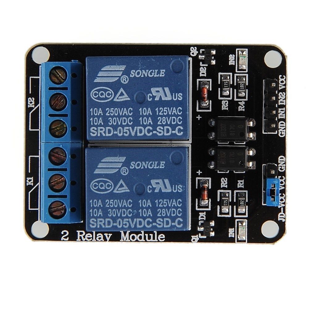
- A relay board – I bought a cheap board from eBay. As well as the two relays the board has opto-isolators that enable control of the (relatively) high-current relay coils from the low-current Arduino digital output.
- An external power supply – The coin-cell battery on the LightBlue Bean doesn’t have enough power to drive the relay boards.
Connecting it up
The relay board I purchased has a four pin header for power and to control the relays. The two outer pins are the +5v supply and the ground (negative) connections. The two inner pins are the control pins for the relays. These pins are active-low, which means that they are connected to ground to activate the relays.
I used a 4 pin crimp-header to connect to the board.

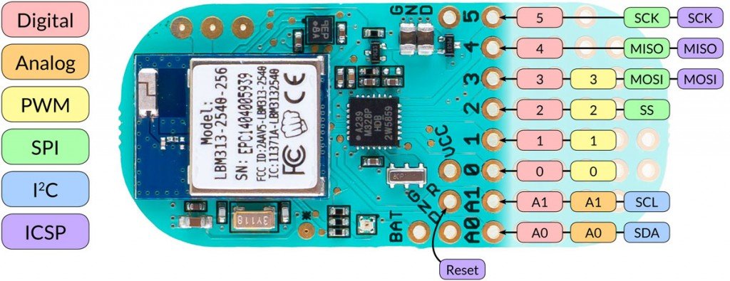
The pinouts for the Bean are shown in the following diagram from the Punch Through site. I just soldered the leads from the relay board connector directly to the Bean.

On the relay board, “Vcc” and “Gnd” connect to a 5V DC power supply. IN1 connects to 0 (Digital output 0) on the Bean. IN2 connects to 1 (Digital output 1) – I am not using the second relay in this project, but I wired it up anyway. Other connections from the Bean are “Bat” and “Gnd” to a pair of AA batteries (for longer life than the coin cell) and “Gnd” to ground on the relay board/power supply to tie the two together.
DO NOT CONNECT THE BEAN TO THE +5V OF THE POWER SUPPLY!
The bean is a 3.3V device and if you connect it to 5V you will let out the magic smoke and your bean will be no more.
If you do want to run everything off the same power supply I recommend one of these neat step-down boards from Pololu.
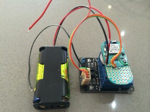
Bringing it all together it looks something like this –
The unconnected red and black wires connect to the 5V supply that powers the relay board. In case you can’t tell from the image, the black wire is doubled up with the green wired in the 4-pin header. The green wire is connected to ground on the Bean.
Since my relay board had two relays, I connected the second relay to port 1 on the Arduino. I have created a separate branch of the BeanLock code that supports the second relay. You can get it in the twoLock branch on GitHub
Part 2 covers the code for the Arduino on the LightBlue bean and Part 3 will cover the iOS application

works perfectly thanks
Can you upload the *.ipa version of IOS code for iphone, I do not have a developer licenses to upload the code but I can upload the *.ipa in to my Iphone